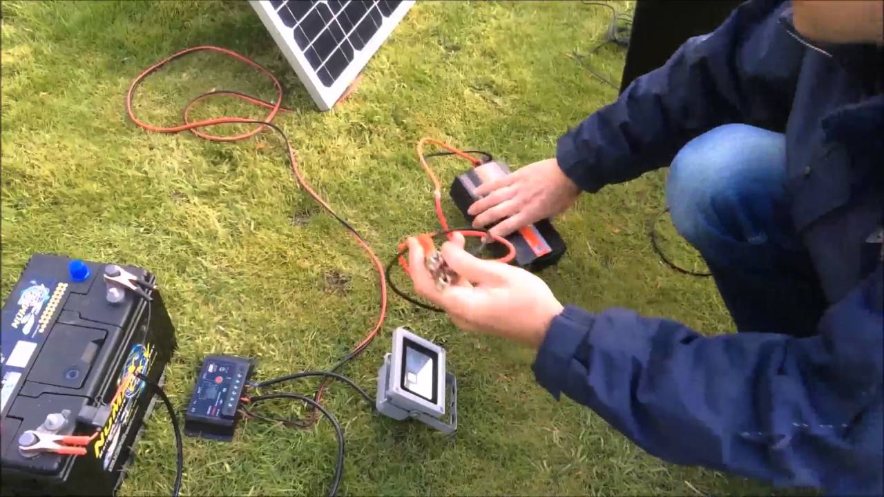
diagram circuit How to Build a Solar Panel Voltage Regulator Charger Circuit Diagram A simple solar panel voltage regulator circuit may be witnessed in the following diagram, the given switch may be used for selecting a battery charging option or directly driving the inverter through the panel. In the above case, the regulator needs to produce around 7 to 10amps of current therefore an LM396 or LM196 must be used in the charger Taking a look at the given solar mppt circuit making use of IC555 we observe that the whole design is essentially put into two levels. The upper voltage regulator stage and the lower PWM generator stage. The upper stage contains a p-channel mosfet which can be placed as a switch and replies to the used PWM info at its gate. Using a 5 watt solar panel or any other solar panel without a voltage regulator actually helps ruin a battery. So I posted this video on how to read the sch
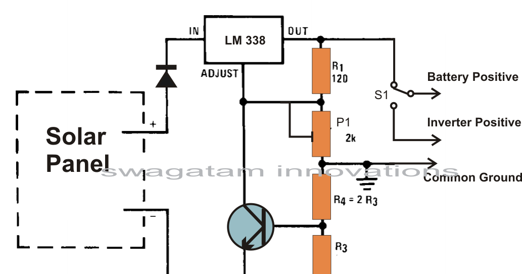
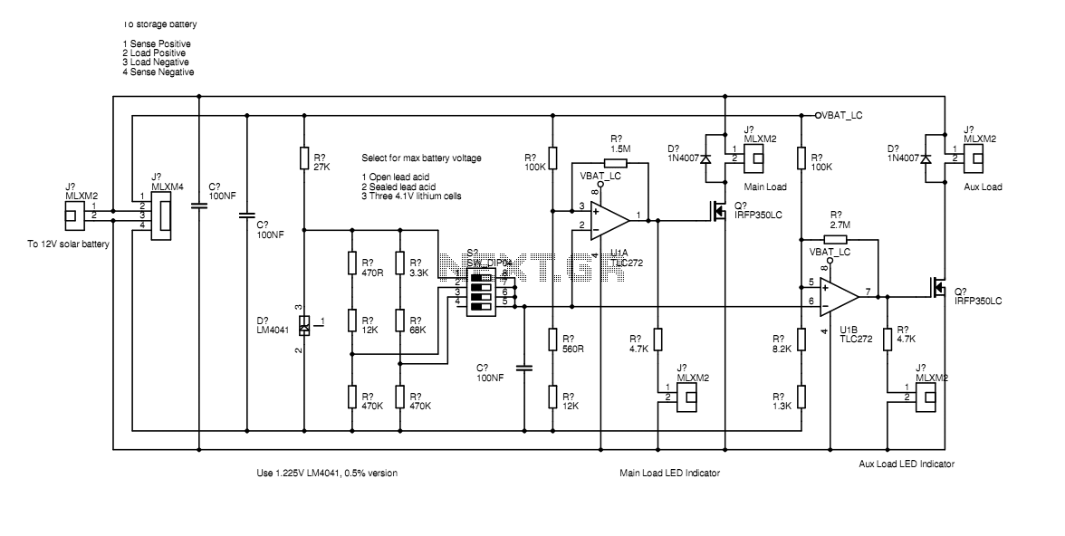
The circuit presented here uses linear shunt regulation. Simply spoken, it burns off all excess energy from the panel, keeping output voltage constant. At times when the solar panel output is equal or greater than the load, and the battery is fully charged, the load gets its power from the panel, while the battery rests at full charge. The battery is charging as shown by the green LED that is on. Op amp A1a turns off transistors Q1-Q3 as the battery terminal voltage approaches the solar panel's open-circuit potential. This state of affairs remains locked until the battery voltage falls below 13.2 V, at which point the battery charging procedure is once more initiated. So I have explained the proposed circuit (solar optimizer) with the help of the following points:The figure shows an LM338 voltage regulator circuit which has a current control feature also in the form of the transistor BC547 connected across adjustment and ground pin of the IC. Opamps Used as Comparators. The two opamps are configured as
How to Make a Simple Solar MPPT Circuit Using IC555 Circuit Diagram
The circuit presented here uses linear shunt regulation. Simply spoken, it burns off all excess energy from the panel, keeping output voltage constant. At times when the solar panel output is equal or greater than the load, and the battery is fully charged, the load gets its power from the panel, while the battery rests at full charge. This device is designed to be a simple, inexpensive 'comparator', intended for use in a solar cell power supply setup where a quick 'too low' or 'just right' voltage indicator is needed. The circuit consists only of one 5V regulator, two transistors, two LEDs, five resistors, two capacitors, and one small battery. Although a 4-V battery is indicated, 4.5 V (3 alkalines in series